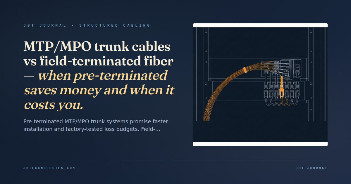
MTP and MPO describe the same connector family — MPO is the international standard (Multi-fiber Push On, IEC 61754-7), and MTP is the commercial designation for a high-performance version manufactured by US Conec. In the field, the two terms are interchangeable. What matters for project decision-making is not the connector name but the system approach: pre-terminated trunk assemblies with factory-polished connectors, or field-terminated connectors installed on the jobsite after the cable is pulled.
Pre-terminated trunk systems arrive at the jobsite with both ends already connectorized. The installer pulls the assembly through conduit, plugs the end modules into the panels, and the link is live — no termination required on site. Field-terminated systems use bulk ribbon fiber cable; the contractor installs connectors after the pull, using fusion splicing or mechanical connectors. The choice is made during design, but the consequences of the wrong choice show up at commissioning.
Polarity methods A, B, and C — the ordering decision you cannot undo
Before a single trunk is ordered, the project needs a polarity plan. TIA-568.3-D defines three polarity methods for MTP/MPO cabling systems, and choosing the wrong one — or mixing methods without documentation — produces crossed or swapped fiber pairs that make every transceiver appear to be looking at dark fiber until someone pulls the assembly and identifies the mismatch.
The three methods:
- Method A (straight-polarity trunk). Each fiber at position N on the A-end connects to position N on the B-end. The connector key faces opposite directions at each end — key-up on the A-end, key-down on the B-end. Method A trunks are the most widely deployed and are typically paired with Type B harness modules, which introduce the required pair reversal at the LC/SC breakout.
- Method B (flipped-polarity trunk). Both ends have the connector key in the same position (both key-up or both key-down). The fiber at position N on the A-end connects to position (13–N) on the B-end — a full inversion across the 12-fiber bundle. Method B trunks use Type A harness modules. They are less common because the inversion creates labeling and troubleshooting complexity.
- Method C (pair-swap trunk). Adjacent fiber pairs are crossed: position 1 goes to position 2, 2 to 1, 3 to 4, and so on. Method C is defined for compatibility with specific transceiver designs that require pair-level swapping. It is rarely specified in new commercial installations.
The loss-budget math
MTP/MPO connectors have higher per-pair insertion loss than LC or SC connectors because the multi-fiber alignment tolerance stack is compounded across 12 or 24 fibers in a single mated pair. TIA-568 sets the maximum insertion loss per MTP mated pair at 0.35 dB. In practice:
| Termination type | TIA max per mated pair | Typical range (new, clean) | Notes |
|---|---|---|---|
| MTP/MPO pre-terminated, factory-tested | 0.35 dB | 0.10–0.25 dB | Factory test certificate included; each assembly serialized |
| MTP/MPO field-terminated, fusion-spliced | 0.35 dB | 0.20–0.50 dB | Depends on splicer condition, ribbon cleave quality, and alignment pin wear |
| MTP/MPO field-terminated, mechanical | 0.35 dB | 0.40–0.75 dB | Higher loss; acceptable for short links, not 40GbE+ with tight budgets |
| LC duplex (for comparison) | 0.10 dB | 0.05–0.10 dB | Used at the harness module breakout, not the trunk connector |
A 40GbE link using 40GBASE-SR4 (parallel optics, 12-fiber MTP) over OM4 has a channel loss budget of 1.9 dB for 100 meters. A typical two-trunk riser path includes: two MTP connector pairs (× 0.35 dB max = 0.70 dB) plus one midpoint interconnect (0.35 dB) plus cable attenuation (negligible at OM4 for 100 m). Maximum channel loss = 1.05 dB, leaving 0.85 dB margin. That budget is comfortable with factory-terminated connectors averaging 0.15 dB. It is tighter with field-terminated mechanical connectors averaging 0.60 dB — leaving 0.25 dB margin, enough to fail the link when a single connector face is contaminated or the ribbon was cleaved at an angle. Reading the OTDR trace on an MTP link turn-up identifies whether elevated loss is at a connector face or in the cable span — critical information that a simple power-meter test doesn’t provide.
Schedule risk and the minimum-order trap
Pre-terminated trunk systems require knowing the exact run lengths before placing the order — in the increments the manufacturer stocks or can custom-produce. Standard stock lengths exist (typically 1 m, 3 m, 5 m, 7 m, 10 m, 15 m), but custom lengths for riser runs between floors are common. Custom-length pre-terminated trunks carry lead times of four to eight weeks. Order a trunk that is 0.5 meters too short for the actual pull path and the choices are: cut and re-terminate the field end (voiding the factory warranty) or order a replacement (another four to eight weeks).
The implication for project scheduling: pre-terminated trunk lengths must be measured from as-built conduit or final rack locations, which happens late in the construction timeline. This is the minimum-order trap — the pull measurement happens when the conduit is installed and racks are positioned, but the factory lead time required to order the trunks means delivery lands during the crunch between rough-in and commissioning, with no float. The schedule discipline described in structured cabling installation practice — pathway planning, rack layout confirmation, cable schedule finalization before procurement — applies directly here: the trunk order cannot proceed until rack-to-rack measurements are confirmed.
Field-terminated systems eliminate the length problem. Bulk ribbon fiber is cut to any length on the day of the pull, and connectors are installed immediately afterward. The trade-off is connector quality variability: field termination on a 24-fiber MTP connector requires precision ribbon cleaving and pin alignment that is not trivial, and quality varies between technicians and between splicing equipment conditions. The hybrid approach used in larger commercial and data-center projects: factory-terminated trunks for the riser backbone (where lengths can be measured from completed conduit) and field-terminated harness modules at the IDF or distribution layer (where lengths vary and tight conduit access makes pre-terminated connector bodies difficult to pull).
Conduit constraints — the pull-through problem
Pre-terminated MTP/MPO trunk assemblies have factory-installed connector bodies that are wider than the cable jacket. A 12-fiber MTP connector body is approximately 13 mm × 7 mm; a 24-fiber housing is slightly larger. For 1-inch conduit with a straight pull, this is manageable with a proper pulling sock and appropriate lubricant. For 3/4-inch conduit or runs with multiple 90-degree sweeps, the connector body can catch on fittings, stick at bends, or require pull forces that exceed the rated cable bend radius.
The consequence is design dependency: pre-terminated trunk systems require conduit that was sized and bent with the MTP connector body in mind. In renovation projects where the conduit is already in place — and was not sized for an MTP housing — the pre-terminated option may not be physically viable without conduit replacement. Field-terminated systems use standard jacketed cable with no connector body during the pull; the connector is installed after the cable is seated in the conduit. This is the case where structured cabling design should identify pathway constraints during the design phase, not after the trunk order arrives at the loading dock.
Where pre-terminated wins
Pre-terminated MTP/MPO trunk systems are the right answer when:
- Run lengths are known and fixed. Purpose-built data centers, new construction with finalized rack layouts, and standardized telecommunications rooms with defined equipment bays have predictable dimensions. The trunk-length problem disappears when the building is designed around the cabling plant.
- Port density is high. A 12-fiber MTP trunk with a 12-LC harness module terminates 12 fibers in a single connection. At data-center scale — thousands of fibers per floor — the labor differential over field termination is substantial and predictable.
- Loss budget is tight. Factory-tested connectors with serialized insertion-loss certificates are the right choice for 100GbE and 400GbE links where the margin between a passing and failing channel is 0.2–0.3 dB. Factory termination is predictable; field termination at that margin is not.
- Turn-up speed matters. A pre-terminated trunk is physically installed in minutes per run. The acceptance test for a factory trunk with a test certificate is faster than the OTDR certification for field-terminated connectors — assuming the polarity method was ordered correctly.
Where field-terminated wins
Field-terminated fiber is the better answer when:
- Run lengths are variable or unknown until after conduit is pulled. Renovation projects, existing buildings with indirect pathways, and facilities where equipment location shifts during construction benefit from the ability to cut and terminate at any length on the day of the pull.
- Conduit access is limited. Existing conduit not sized for an MTP connector body, or pathways with multiple pulls sharing space, makes field termination the practical choice regardless of the theoretical quality advantage of factory termination.
- A qualified terminator is on site. A fiber contractor with a calibrated fusion splicer, precision ribbon cleaver, and OTDR certification can match factory insertion-loss performance consistently. The quality concern is real for mechanical field termination on multi-fiber connectors — where pin alignment wear and cleave variation compound across every fiber in the bundle. Fusion splicing does not carry the same risk.
The OTDR turn-up — what gets caught last
Regardless of which termination method is used, every MTP/MPO installation should be OTDR-tested at acceptance, not just power-meter tested. The power meter measures end-to-end insertion loss; the OTDR identifies where the loss is located. A channel that passes the power meter test may have an elevated-reflectance connector face that will degrade as the end-face oxidizes, or a micro-bend event in the cable that adds loss incrementally over the first year of operation. The OTDR trace for a pre-terminated trunk with a factory certificate provides a commissioning baseline; any deviation from that baseline at site testing is evidence of installation damage during the pull.
The commissioning surprises that appear most often on MTP/MPO installations: wrong polarity method ordered (discovered when the switch cannot establish a link); trunk 0.3 meters short on a constrained pull path (discovered when the connector body won’t reach the panel after the cable is seated); field-terminated connectors with elevated insertion loss that passed the visual inspection but show localized reflectance on the OTDR. All three are avoidable with upfront planning — and with the right fiber type specified for the transmission distance and data rate before the trunk order is placed, not at commissioning.
Planning a fiber backbone for a new buildout or data center?
We design and install MTP/MPO backbone systems — specifying polarity method, trunk lengths, loss budgets, and conduit sizing before the purchase order, not after. OTDR-certified acceptance testing on every run. Serving Atlanta and the Southeast.