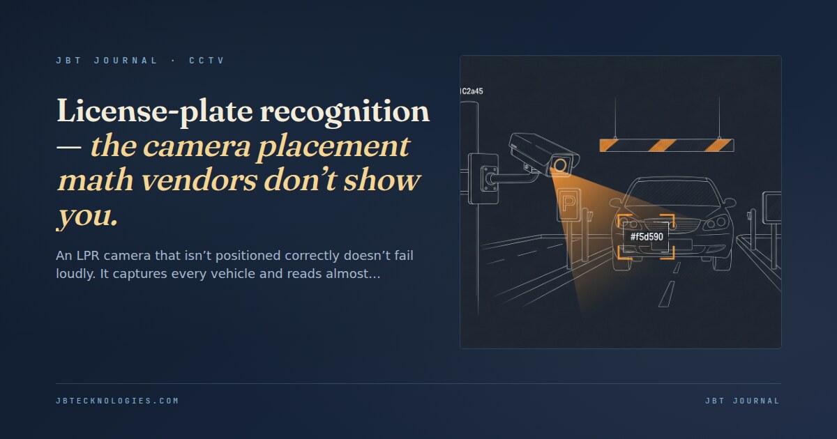
License plate recognition is a feature, not just a camera type. The same sensor that records every vehicle entering a parking facility will read effectively zero plates if the physical placement geometry is wrong. The failure mode is insidious: the camera appears functional, the video is clear, the plates are visible to the human eye on playback, and the LPR engine returns nothing because the captured image does not meet the pixel density, angle, or lighting threshold the algorithm requires.
Understanding the placement constraints before the camera mount is selected — and before conduit is run — is the difference between an LPR deployment that works on day one and one that generates an expensive engineering revisit three months after installation. The broader CCTV design decisions that govern camera selection, storage, and analytics integration are relevant context here; the video retention and storage post covers the analytics-led storage approaches that LPR systems frequently leverage to extend effective retention without proportional disk spend.
The angle of incidence constraint — why it matters more than most specs state
License plate recognition algorithms are designed around a relatively narrow angular tolerance for capturing plate text. The maximum usable capture angle (the angle between the camera line-of-sight and the plane of the license plate) is typically 30–35 degrees for most LPR engines. Beyond that threshold, character distortion from perspective foreshortening causes false reads or no reads, even when the plate is clearly visible to a human observer.
In practice, this means:
- A camera mounted perpendicular to the lane centerline (looking straight across traffic) will almost never read plates because the plate is nearly parallel to the camera sensor. Effective zero angle of incidence on the plate from that mounting geometry.
- A camera positioned directly overhead reads plates poorly because the vertical angle to the horizontal plate exceeds the tolerance. Overhead mounting works for general vehicle detection; it does not work for LPR.
- The optimal capture position is approximately 15–30 degrees off the vehicle’s line of travel, at a vertical angle of 15–30 degrees above horizontal to the plate. This geometry puts the plate face close to perpendicular to the camera sensor while maintaining a field of view that allows adequate dwell time in the capture zone.
Pixel density — the minimum that most site plans don’t calculate
LPR engines specify a minimum pixel-per-foot (PPF) or pixel-per-meter requirement at the license plate for reliable character recognition. Most commercial LPR software requires a minimum of 40–80 pixels across the width of a standard license plate (approximately 12 inches) for reliable recognition. That translates to a minimum horizontal pixel density at the plate distance.
A camera with a 1/3” sensor and 2MP resolution at 1920×1080 has a certain field of view at a given focal length. If the camera is positioned 60 feet from the capture point and uses a wide-angle lens covering 40 feet of horizontal width at that distance, the 1920 horizontal pixels are spread across 40 feet — producing 48 pixels per foot. A 12-inch plate occupies 4 pixels at that density. That is roughly 1/10th the minimum pixel requirement for most LPR engines. The camera records the vehicle; the LPR engine reads nothing.
Calculating the required focal length for a target capture distance is the critical geometry step that most camera selections skip:
- Determine the capture distance (the distance from the camera to the vehicle when the plate is in the optimal angle window). For lane-entry LPR, this is typically 20–40 feet.
- Calculate the field of width required at that distance to frame the vehicle and allow for lane position variation. Typically 10–14 feet for a single lane.
- Calculate the required focal length: lens focal length (mm) = sensor width (mm) × capture distance / field width. For a 1/3” sensor (4.8mm horizontal) capturing a 12-foot lane at 30 feet: focal length = 4.8 × 30/12 = 12mm.
- Verify pixel density: at 12mm focal length, 1920 horizontal pixels covering 12 feet of field = 160 pixels per foot = approximately 160 pixels across the 12-inch plate. Adequate for most LPR engines.
Lighting conditions — where LPR systems most commonly fail at night
License plate reflectivity varies significantly by state, material age, and plate condition. Night capture requires adequate illumination of the plate to produce the contrast ratio the LPR algorithm needs. Natural ambient light in parking facilities is typically insufficient; active IR illumination or white-light supplementation is required for reliable nighttime LPR.
The illuminator and the camera must be co-located or precisely aimed at the same capture zone. An IR illuminator mounted at a different position than the camera illuminates a different zone than the camera is capturing; the plate that the camera sees may not be in the illuminator’s beam. The illuminator beam angle must encompass the camera’s capture zone with at least 30% overlap margin. For daytime-only applications where headlight glare is the primary problem (parking lot entries facing west), an auto-exposure camera with WDR (wide dynamic range) capability handles the glare without supplemental illumination. WDR requirements differ from LPR requirements but frequently interact in mixed-condition deployments.
The IR vs. starlight camera tradeoff for low-light capture in general parking contexts — not specifically LPR — involves different considerations than the LPR illumination math. Our CCTV design services address lighting and camera selection as a combined system decision, not as separate specifications.
Lane configuration and multi-lane LPR
Most LPR deployments involve a defined capture zone — a gate lane, entry ramp, or controlled chokepoint where one vehicle passes at a time. For open-lot applications or multi-lane entries without a physical gate, LPR performance degrades substantially because the capture window must cover a wider field, reducing pixel density per plate and increasing the probability of occlusion from adjacent vehicles.
| Deployment type | Typical read rate | Key placement constraint |
|---|---|---|
| Single gated lane (< 15 mph) | 90–98% under correct placement | Angle, pixel density, and illumination as above |
| Single ungated lane (access road, 5–15 mph) | 80–92% | Speed introduces motion blur; shutter speed must be ≥ 1/500s in low light |
| Multi-lane ungated (parking lot open entry) | 60–80% | Pixel density inadequate for far-lane plates at wide field coverage; requires per-lane cameras |
| Highway / freeway (> 35 mph) | Requires specialized high-speed LPR platform | Standard commercial LPR cameras are not rated for highway speeds |
For multi-lane applications where per-lane cameras are not feasible, wide-angle LPR engines with AI-based plate detection from lower pixel densities exist but carry higher software licensing costs and typically lower read-rate guarantees than lane-specific deployments. The NDAA compliance dimension of camera selection — which affects which manufacturers are available for LPR applications in federally-adjacent facilities — is covered in the NDAA Section 889 camera compliance post. The intersection of NDAA compliance and LPR system selection limits the available platforms in ways that the camera vendor’s spec sheet may not disclose.
What to verify before the camera is ordered
Before an LPR camera is specified or purchased for a commercial installation, four geometric parameters must be confirmed from site measurements, not assumed from typical specifications:
- Actual capture distance at the optimal angle geometry (drive the lane, measure where the capture zone falls)
- Required focal length for minimum pixel density at that capture distance and sensor size
- Illumination plan that co-locates the camera field and the illuminator beam at night
- Ambient light level at night during actual operating conditions (not spec-sheet estimates)
Site-verified LPR designs consistently outperform spec-sheet designs on initial read-rate. The cameras are the same; what changes is whether the placement geometry was designed or assumed.
Designing a license plate recognition system in Atlanta or the Southeast?
We design and install LPR camera systems for commercial parking, access control, and security applications in Atlanta and the Southeast — with the placement geometry and lighting design that determines read rate on day one.