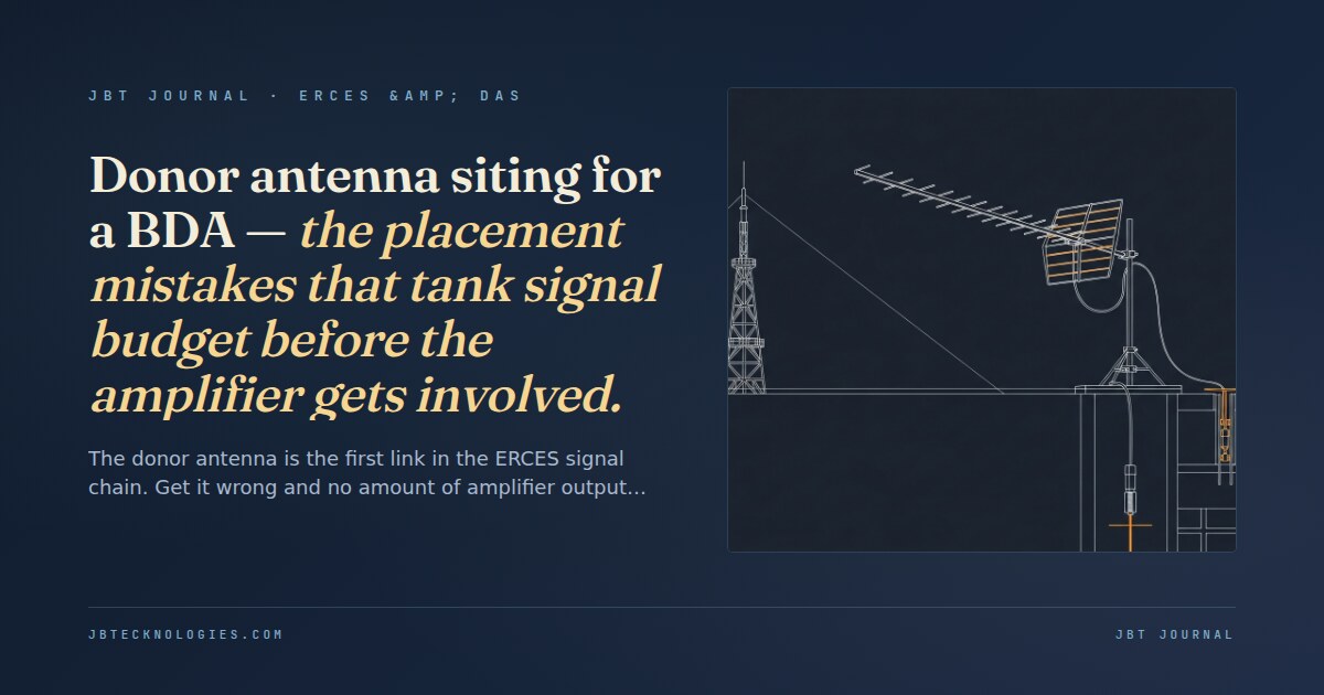
The donor antenna is not a formality. It is the single point in an ERCES installation where the signal budget is either built or destroyed, before the bi-directional amplifier is even powered on. A BDA can add 70–80 dB of gain. A poorly sited donor antenna can easily consume 15–25 dB of that headroom in avoidable losses, leaving the amplifier fighting a signal deficit rather than amplifying a usable input.
Most ERCES design conversations focus on the in-building distribution side: antenna density, cable loss budgets, splitter trees, critical-area coverage. The donor link is treated as a checkbox item. In practice, it is the most consequential placement decision in the system design, and the mistakes made there are often discovered only at the AHJ walk test. For an overview of how the complete ERCES system fits together from donor to distributed antenna, the ERCES primer covers the full signal path and what a compliant installation requires.
Understanding the donor link budget
The donor link budget is the arithmetic of signal available at the BDA input. It starts with the public-safety tower’s effective radiated power (ERP) at the relevant frequency, subtracts free-space path loss over the distance to the building, and adds the gain of the donor antenna while subtracting cable loss between the antenna and the BDA. What remains is the received signal level (RSL) at the BDA input.
NFPA 1225 and IFC 510 both require a minimum donor signal strength at the BDA input — typically −70 dBm for a Class B BDA and −60 dBm for some Class A configurations. Most BDA manufacturers specify a minimum input signal of −75 dBm to −60 dBm for rated output performance. Below the minimum, the amplifier cannot produce its rated output power regardless of gain setting. Every dB lost in the donor link is a dB the amplifier cannot recover.
Line-of-sight — the most important variable and the most often assumed
Line-of-sight between the donor antenna and the public-safety tower is not guaranteed by proximity. Buildings between the site and the tower, rooftop mechanical equipment, water towers, and even tree lines on a city block can break the line-of-sight path and add 10–30 dB of additional diffraction loss. The assumption that a nearby tower means adequate signal at the rooftop is one of the most common design errors in ERCES installation.
The correct approach is a rooftop signal survey before the donor location is fixed. Survey the rooftop at the proposed antenna height (typically 10–15 feet above the roof surface on a mast), measuring received signal strength at several candidate locations. What seems like a minor difference in placement — 20 feet laterally on the same rooftop — can yield a 5–10 dB signal variation due to rooftop equipment blockage or Fresnel zone clearance. The frequency coordination process and its relationship to surveying is covered in detail in the FCC Form 601 and frequency coordination post: confirming which frequencies need to be surveyed before the rooftop work happens saves a second trip.
The Fresnel zone is the elliptical region around the direct path between the donor antenna and the tower within which obstructions cause significant signal loss. For a 700 MHz path, the first Fresnel zone radius at the midpoint of a 1-mile path is approximately 60 feet. A building or structure that clears the straight-line path by only 10 feet may still be inside the Fresnel zone and causing measurable diffraction loss. Low-frequency public-safety bands (VHF/low UHF) have larger Fresnel zones than 700/800 MHz bands and are more sensitive to terrain and structure obstructions at medium distances.
Multipath and its effect on donor signal quality
Urban rooftops are multipath environments. The donor signal arrives at the antenna not just from the direct path but also as reflections off nearby buildings, mechanical equipment, and rooftop surfaces. When the direct path and one or more reflected paths arrive at the antenna with similar amplitude but different phase, they can partially cancel, reducing the effective received signal. This cancellation is frequency-dependent and can create 10–15 dB nulls in specific frequency bands on an otherwise clear rooftop position.
Multipath problems are characteristically difficult to diagnose because they are invisible on a standard signal-strength survey that measures only average received power. A spectrum analyzer or a signal-quality measurement that captures the flatness of the received signal across the relevant frequency band is required to identify multipath nulls. On a congested urban rooftop, 3–5 feet of antenna position change can move from a multipath null to a clean signal path — which is why rooftop surveys should measure multiple positions rather than a single candidate location.
Antenna gain and polarization matching
Donor antennas for ERCES are typically directional (Yagi, log-periodic, or panel) aimed at the primary donor tower. The antenna gain specified in the link budget must match the actual gain at the relevant frequency band. Antenna gain is specified at the design frequency; at the edges of a multi-band public-safety system (e.g., a combined 700/800 MHz antenna), the gain at the band edges may be 2–4 dB lower than the peak gain at mid-band. Using peak-gain figures for budget calculations at the band edges will produce an optimistic link budget that the real installation will not achieve.
Polarization mismatch between the donor antenna and the tower is an additional loss source that is rarely checked in the field. Most public-safety tower antennas are vertically polarized. Tilting a donor antenna during installation — even a few degrees off vertical due to a non-level mounting surface — introduces polarization mismatch loss. At 10 degrees of tilt, the mismatch loss is approximately 0.3 dB. At 45 degrees, it exceeds 3 dB. On a flat rooftop with a level mast, this is not a concern; on a pitched roof or a non-standard mount, it is worth verifying with an inclinometer before finalizing the installation.
Cable runs from rooftop to BDA — where planned loss becomes actual loss
The cable run from the donor antenna on the roof to the BDA headend inside the building is a fixed, calculable loss. What is less fixed is the actual length and routing of that run, which in retrofit installations often increases significantly from the design estimate as the cable follows available pathways through mechanical rooms and equipment rooms rather than the direct vertical route assumed at design.
| Cable type | Loss at 800 MHz | 100-foot run loss | Notes |
|---|---|---|---|
| LMR-400 | ~1.3 dB/100 ft | 1.3 dB | Standard jumper for donor antenna runs; practical up to ~150 ft |
| LMR-600 | ~0.8 dB/100 ft | 0.8 dB | Preferred for runs exceeding 100 ft; stiffer installation |
| ½" Heliax (FSJ4-50B) | ~0.7 dB/100 ft | 0.7 dB | Flexible Heliax; good for longer runs with bend requirements |
| 7/8" Heliax | ~0.4 dB/100 ft | 0.4 dB | Low-loss backbone; requires straight pathways, limited bend radius |
Add connector losses (0.1–0.2 dB per connector pair at 800 MHz) and lightning suppressor insertion loss (1–2 dB for most ICB or gas-tube suppressors). A 150-foot LMR-400 run with two connectors, a lightning suppressor, and a grounding block commonly produces 4–5 dB of total cable assembly loss. In a link budget that needs −70 dBm at the BDA input from a −72 dBm rooftop signal, that cable loss is the margin that determines whether the system meets spec or doesn’t.
The intermodulation problem with co-sited antennas
On rooftops that already host cellular DAS, commercial carrier antennas, or broadcast equipment, donor antenna placement must account for interference from co-sited transmitters. Strong out-of-band signals can intermodulate within the BDA, creating spurious products on the public-safety frequency that the amplifier then re-broadcasts. The problem is exacerbated when the donor antenna is placed close to a transmitting antenna for a different service.
NFPA 1225 requires that ERCES BDA systems not cause interference to the host public-safety radio system. An intermodulation product on the public-safety frequency coming from the BDA is not just an inspection failure — it is an active impairment to first responder communications in the area. Minimum separation distances between the donor antenna and any transmitting antenna on the same rooftop depend on the transmitter power and the frequency offset; many manufacturers specify a minimum 10-foot separation from any co-located transmitter, which may require roof space planning that is not reflected in the architectural drawings. For buildings that need both ERCES and a commercial carrier DAS, the separation requirements and the shared-infrastructure options are one of the first design coordination items between the two systems. Our ERCES installation services include the rooftop survey and donor link design as part of the complete project scope — not as an afterthought once the BDA has already been ordered.
What a proper donor antenna survey looks like
A pre-design donor antenna survey should cover:
- Receive signal strength at multiple rooftop positions, at the proposed antenna mounting height, using a calibrated test receiver on the exact public-safety frequencies the building must support. Multiple positions across the rooftop, not a single measurement.
- Signal quality check (spectrum flatness across the band) to identify multipath nulls at each candidate position.
- Rooftop obstruction mapping — identifying equipment, structures, and other antennas that may shadow the primary positions or require antenna mast height adjustment for Fresnel zone clearance.
- Cable pathway routing from each candidate antenna position to the proposed BDA headend location, with measured distances and an accurate cable loss calculation including connectors and in-line devices.
- Interference assessment — identifying any co-sited transmitters and calculating minimum separation requirements.
Buildings that skip the rooftop survey and assume adequate donor signal from proximity to a tower frequently discover the real donor conditions at commissioning — when the AHJ is present for the walk test and the BDA cannot produce rated output because the donor input is 8 dB below the minimum spec. At that point, the fix is a mast extension, a cable rerouting, or a second survey trip — all on a timeline that the CO schedule did not budget.
Need an ERCES design that starts with a real donor site survey?
We conduct rooftop signal surveys, donor link budgets, frequency coordination, and complete ERCES design-build for commercial buildings nationwide. The donor antenna is where we start, not where we finish.